Point loads are concentrated loads applied along the span of a member or the edge of a wall panel. Defining point loads may be accomplished graphically or in the spreadsheets. See Drawing Point Loads below to learn how to draw joint loads graphically.
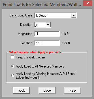
To apply point loads, enter the load direction, magnitude, and location. Make sure that you are careful to enter the correct BLC number that you want the loads assigned to.
Note:
To apply the load to just a few elements choose
To apply the load to a selection, choose
Note:
Please see the Moving Loads topic for more information on how to create static point loads from a specific moving load step location.
The Point Load Spreadsheet records the point loads for the member elements
and may be directly accessed by![]() Point Loads
on the Spreadsheets menu
Point Loads
on the Spreadsheets menu
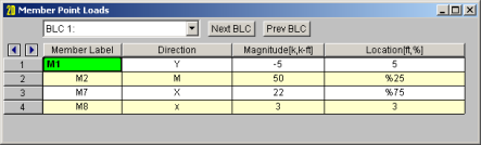
The first column contains the label of the member or wall panel to receive the load.
The direction in the second column represents the direction of the load as one of the options mentioned above.
The load magnitude is recorded in the third column. The units for the magnitude are listed at the top of the column, depending upon whether the load is a force or a moment.
The fourth column contains the location of the load. The location is the distance from the I-joint of the member and is unaffected by any member offsets. The location of the load may be defined as a percentage of member length. To define the distance from the I-joint as a percentage of member length, enter the percentage value (0 to 100), preceded by the symbol "%". For example, a load in the center of the member would be defined with a location of "%50". Using a percentage value is handy if the member's length will be changing due to editing of the model coordinates and you wish to have the load some proportional distance from the I end.
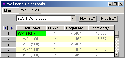
The Wall Panel Point Loads Spreadsheet records the point loads on your wall panels. Note that the loads are specific to the BLC's and that you can use the drop-down list to scroll between your various load cases. The columns in the spreadsheet are the same as the member point loads spreadsheet.
x, y - Load applied in local x and ydirection
X, Y - Load applied in global X, and Y direction
M - Moment about global axis